
Last updated: July 23, 2026
Key Takeaways for Production-Ready Sheet Metal
- Align CAD designs with actual press brake and laser constraints from the start to eliminate costly rework cycles and ensure first-article success.
- Apply consistent DFM rules such as constant wall thickness, material-appropriate bend radii, proper reliefs and validated K-factors to keep parts on spec and reduce tooling changes.
- Position holes, slots and hardware at safe distances from bend lines and validate bend sequence and springback to prevent distortion and cracking during forming.
- Use a three-stage prototyping workflow with proof-of-concept, engineering validation and production candidate builds to surface issues early while changes remain inexpensive.
- Partner with Fabcon for ISO-certified fabrication, finishing and assembly under one roof to move designs from CAD to production-ready parts with confidence.
DFM Rules That Keep Parts on Spec
These rules address the most common failure points between CAD intent and fabricated reality. Each rule targets a specific constraint from press brake tooling, laser cutting or material behavior, and consistent use reduces dimensional failures and rework after first-article inspection.
- Maintain constant wall thickness. Mixing gauges on a single part forces multiple setups and introduces springback inconsistency across the blank.
- Use material-appropriate inside bend radii. Minimum inside radii vary by alloy. Apply the same radius to all flanges on a part to reduce tool changes.
- Add bend reliefs at every flange intersection. Relief width must equal at least one material thickness and depth must equal at least the bend radius to prevent tearing at box corners.
- Respect hole-to-bend distances. Holes and slots must sit at least 2.5 times material thickness plus the inside bend radius from the bend line to prevent ovalization during forming.
- Minimize bend count. Each bend requires a brake setup, tool change and handling step, so bend count becomes a primary cost driver in prototype quotes.
- Specify standard tooling radii. Drawings should specify the inner bend radius and match radii across all bends on multi-bend parts to enable use of a single punch and die set.
- Validate bend allowance and K-factor in CAD. K-factor values and bend angle tolerances are practical defaults and work best when confirmed against actual forming behavior instead of software-generated assumptions.
- Apply tolerances by function, not habit. Tolerances on features across multiple bends can be looser than those on a single flat surface. Tightening noncritical features adds cost without benefit.
- Orient critical bends perpendicular to grain direction. Bending parallel to grain can require a larger bend radius and increases cracking risk in aluminum and stainless alloys.
- Maintain minimum flange length. A practical baseline for minimum flange length is four times material thickness. Shorter flanges increase angle drift and tool marking during press brake forming.
Applying these rules consistently requires validating designs against real press brake and laser constraints before cutting begins. Request a DFM review from Fabcon's engineering team to confirm bend radii, hole placements and K-factors match production constraints.
Sheet Metal Bending Design Guidelines
Bend radius selection is the most consequential DFM decision on a formed part. For air bending with standard tooling, the minimum inside bend radius is one times material thickness for mild steel, 1.5 to 2 times material thickness for 304 stainless and one times material thickness for 5052-H32 aluminum. Harder alloys such as 6061-T6 require more conservative radii to avoid outside-surface cracking.
K-factor ranges for accurate flat-pattern development are 0.41 to 0.44 for mild steel, 0.40 to 0.45 for aluminum and 0.44 to 0.50 for stainless steel. These ranges act as starting points, and actual K-factor values must be validated against bend behavior in the specific material and thickness rather than assumed from nominal CAD defaults. Using validated values in the bend allowance formula prevents flat-pattern errors that cause dimensional failures after forming.
Powder coating also affects mating features. A typical coating adds thickness per surface and can reduce clearance on tabs, slots and threads if masking zones are not defined on the drawing.
Bend relief corners should incorporate a minimum radius of 0.5 mm to reduce stress concentration and avoid sharp notches that initiate tearing during forming.
Hole-to-Bend Distances and Weld Access
Correct hole placement protects fastener fit and assembly alignment after forming. Holes placed inside the deformation zone distort into ovals during forming, which prevents proper fastener seating and creates assembly mismatch. The minimum distance established earlier keeps holes outside this deformation zone and preserves roundness.
Self-clinching PEM inserts require additional clearance. Keep PEM hardware at least two times hole diameter from the bend line to ensure proper seating and avoid interference with forming.
Weld access must be planned alongside hole placement. A DFM review for sheet metal production should check welding access and distortion alongside bend radius, hole distance and tolerance stack-up. Welded assembly prototypes expose distortion risks and access issues that flat-part drawings do not reveal.
Post-finish weld repairs after powder coating or plating erase efficiency gains from good fabrication and often require a sequence of finishing, reworking and refinishing. Avoiding those repairs protects both schedule and cost.
Splitting flat-part cutting and forming between two different shops typically leads to dimensional inaccuracies because the forming fabricator lacks access to the original K-factors, bend deductions and setbacks used during cutting. Keeping fabrication, finishing and assembly under one roof eliminates that risk.
Bend Sequence and Springback Considerations
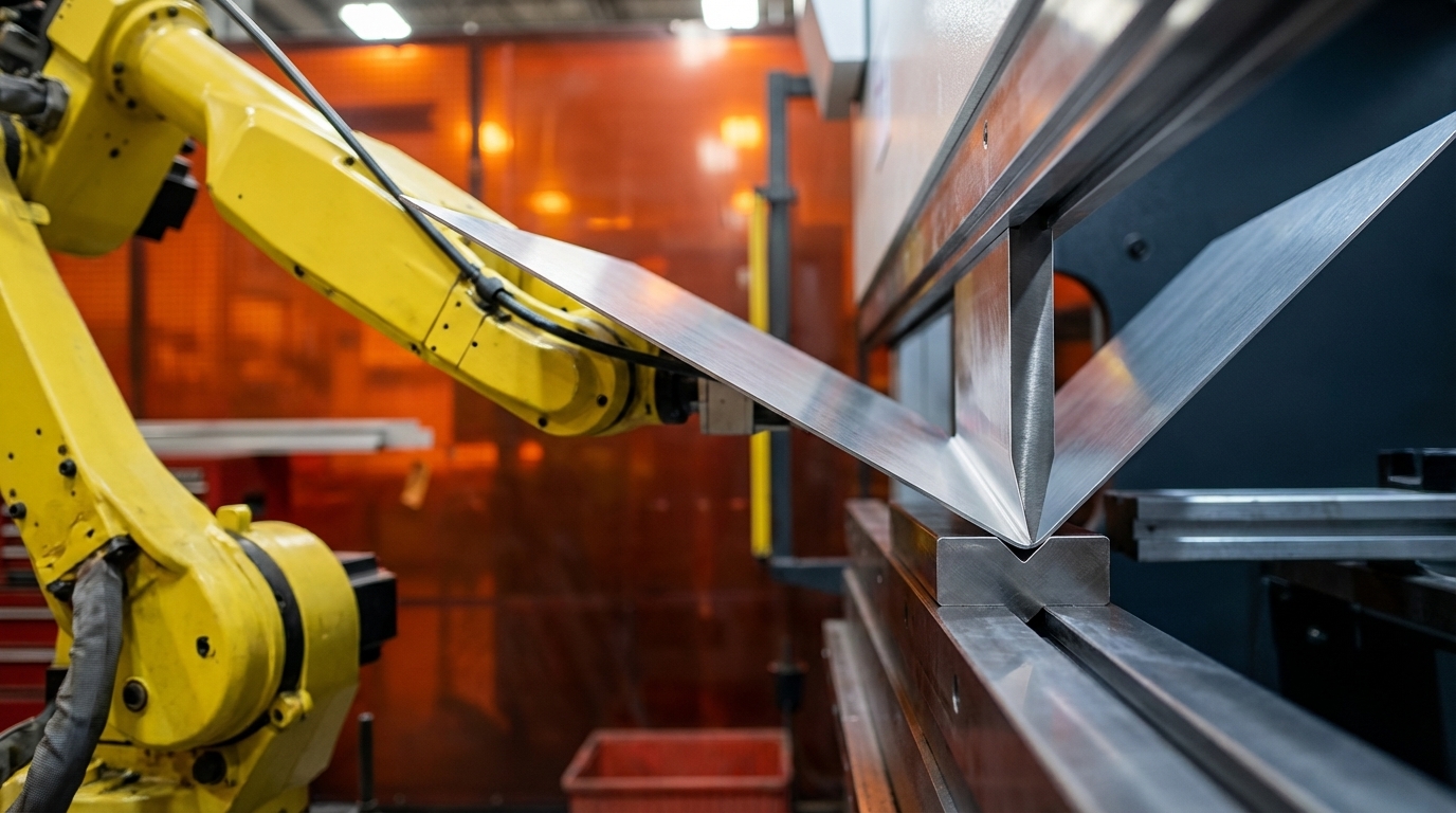
Bend sequence determines whether a part can be formed and how consistently it runs in production. Complex geometries with multiple flanges must be sequenced so each successive bend preserves tool access for the next. Prototyping that mirrors eventual production routing surfaces process issues early. A part hand-bent on a manual brake proves geometry but reveals nothing about behavior on a CNC press brake in a robotic cell at rate.
Springback varies significantly by alloy and must be accounted for in bend programming. Typical springback after bending is 1 to 2 degrees for 5052/1100 aluminum, 3 to 6 degrees for 6061-T6 and 7075-T6, 2 to 3 degrees for cold-rolled mild steel and 4 to 7 degrees for 304 stainless steel. Overbending to compensate for springback works best when validated against actual material behavior instead of nominal values.
DFM Collaboration Checklist
Involving the fabricator as soon as preliminary drawings exist allows early identification of issues in tolerance specifications, material selection, bend allowances and assembly considerations. The following checklist covers the items a fabricator should review before any cutting begins. Working through these items systematically keeps CAD assumptions aligned with actual tooling capabilities and confirms that the flat pattern will form correctly without dimensional drift or feature distortion.
- Inside bend radii confirmed against material grade and thickness
- K-factor and bend allowance validated in the flat pattern
- Hole and slot distances from bend lines verified
- Bend reliefs added at all flange intersections
- Minimum flange lengths confirmed at 4T or greater
- Critical bends oriented perpendicular to grain direction
- Weld seam locations and access confirmed on the drawing
- Coating buildup and masking zones defined
- Tolerances assigned by feature type and functional need
- Datum scheme and GD&T callouts complete
- Hardware part numbers and insertion access confirmed
- STEP file, PDF drawing and material grade submitted together
Fabcon's engineering and quoting teams work through this checklist with customers before production begins, which reduces rework and compresses development timelines. Submit your design to have the team validate it against this checklist before cutting begins.
Prototype 1 to 3: From Proof-of-Concept to Production Candidate
A three-stage prototyping workflow validates bend allowance, K-factor and tolerances at the lowest cost per iteration. Each stage builds confidence in geometry, function and production readiness.
Prototype 1 – Proof of Concept. The goal is geometry and fit verification using production-intent material and processes. The practical sequence is laser cut to CNC bend to hardware insertion to weld if needed to finish. At this stage, teams check tolerances against the drawing using calipers and height gauges.
Issues with bend sequence, hole distortion and weld access surface during this first build while changes remain inexpensive. Early corrections here prevent costly redesigns later.
Prototype 2 – Engineering Validation. A small pilot batch confirms assembly integration, tolerance stack-up across multiple bends and finish compatibility. This stage includes engineering assembly and functional testing, design revision if necessary and approval of a golden sample.
Reducing iteration count through early DFM application, use of standard materials and relaxed noncritical tolerances is one of the highest-impact methods to shorten overall time from CAD to validated prototype.
Prototype 3 – Production Candidate. A controlled scaling path moves through DFM review, prototype, pre-production pilot, first article inspection per AS9102 and production part approval. The pilot run confirms cycle time, material yield, fixture performance, first article inspection results, finish quality, hardware installation and rework rate.
Moving from Prototype to Production Sheet Metal
Material and process consistency across the transition protects performance and cost targets. Aluminum, stainless steel and cold-rolled steel behave differently in forming, welding, springback and surface finish, so substituting materials in prototypes can mislead teams on strength, part cost and production viability.
Fabcon's ISO 9001:2015 and AS9100D certified quality systems govern every stage of the build and provide full traceability from prototype through production. Fabrication, finishing and light electromechanical assembly under one roof eliminates the vendor handoffs that introduce dimensional inaccuracies and schedule risk.
Frequently Asked Questions
Does early DFM review increase project cost
Early DFM review reduces total project cost by catching design issues before fabrication begins. Addressing a bend radius or hole placement problem at the drawing stage costs a fraction of the same correction after parts have been cut, formed and finished.
Rework on coated or plated parts often requires stripping the finish entirely, which can make the correction more expensive than scrapping and restarting. Investing in a DFM review at the outset compresses iteration count and protects the overall program budget.
Can a single fabrication partner handle prototype through production scaling
A vertically integrated partner that performs fabrication, finishing and assembly internally can support a program from the first prototype through mid-volume production without vendor transitions. This continuity preserves the K-factor assumptions, bend deductions and process parameters established during prototyping and reduces the risk of dimensional drift when volumes increase.
Fabcon's agile production cells adapt to changing volumes and mixed SKUs without the high minimums or rigid onboarding requirements of large contract manufacturers.
What quality certifications should a sheet metal fabrication partner hold for infrastructure and technology programs
ISO 9001:2015 certification establishes a documented quality management system with traceability across all production stages. AS9100D certification adds aerospace-grade requirements for risk management, configuration control and first article inspection documentation.
For programs in defense, medical or energy storage applications, these certifications provide the audit trail and process discipline that procurement and compliance teams require. Fabcon holds both certifications and applies their requirements across every program, from prototype to full-rate production.
How does consolidating vendors affect lead time reliability
Fragmented supply chains introduce schedule risk at every handoff point. When cutting, forming, finishing and assembly are distributed across multiple vendors, each transition adds coordination time, shipping delays and the potential for dimensional inaccuracies caused by differing process assumptions.
A single partner that controls all operations internally removes those variables and provides a single point of accountability for delivery commitments. Programs with compressed launch timelines benefit most from this consolidation because there are no third-party schedules to accommodate.
Conclusion and Call to Action
Ten DFM rules covering bend radii, relief features, hole placement, K-factor validation, grain direction, flange length, tolerance strategy, standard tooling, bend count and early fabricator involvement address the root causes of first-article failures in custom sheet metal parts. A three-stage prototyping workflow that moves from proof-of-concept through engineering validation to a production candidate surfaces springback, distortion and tolerance stack-up issues while changes remain inexpensive.
Fabcon brings fabrication, finishing and light electromechanical assembly together under one roof and applies ISO 9001:2015 and AS9100D certified quality systems from the first prototype through scaled production. Early DFM collaboration with Fabcon's engineering team aligns designs to actual press brake and laser constraints before cutting begins, which reduces rework and protects launch timelines.
Start your DFM review to move a current design from CAD to production-ready parts with confidence.