Key Takeaways for Sheet Metal Enclosure DFM
-
Enclosure design DFM sheet metal practice resolves manufacturability constraints early, eliminating rework cycles, tolerance stack-up failures and vendor handoffs that delay launches.
-
Market growth in North American fabricated metal services comes from infrastructure spending and semiconductor reshoring, so DFM-ready designs support faster production throughput.
-
Material-specific bend radii, hole-to-bend clearances and bend relief rules prevent cracking, distortion and assembly interference in sheet metal enclosures.
-
Transitioning from prototype to production with the same fabricator preserves validated tooling, reduces supplier-switching risk and maintains consistent quality and traceability.
-
Fabcon delivers vertically integrated sheet metal fabrication, finishing and assembly under ISO 9001:2015 and AS9100D certifications, which accelerates enclosure program launch.
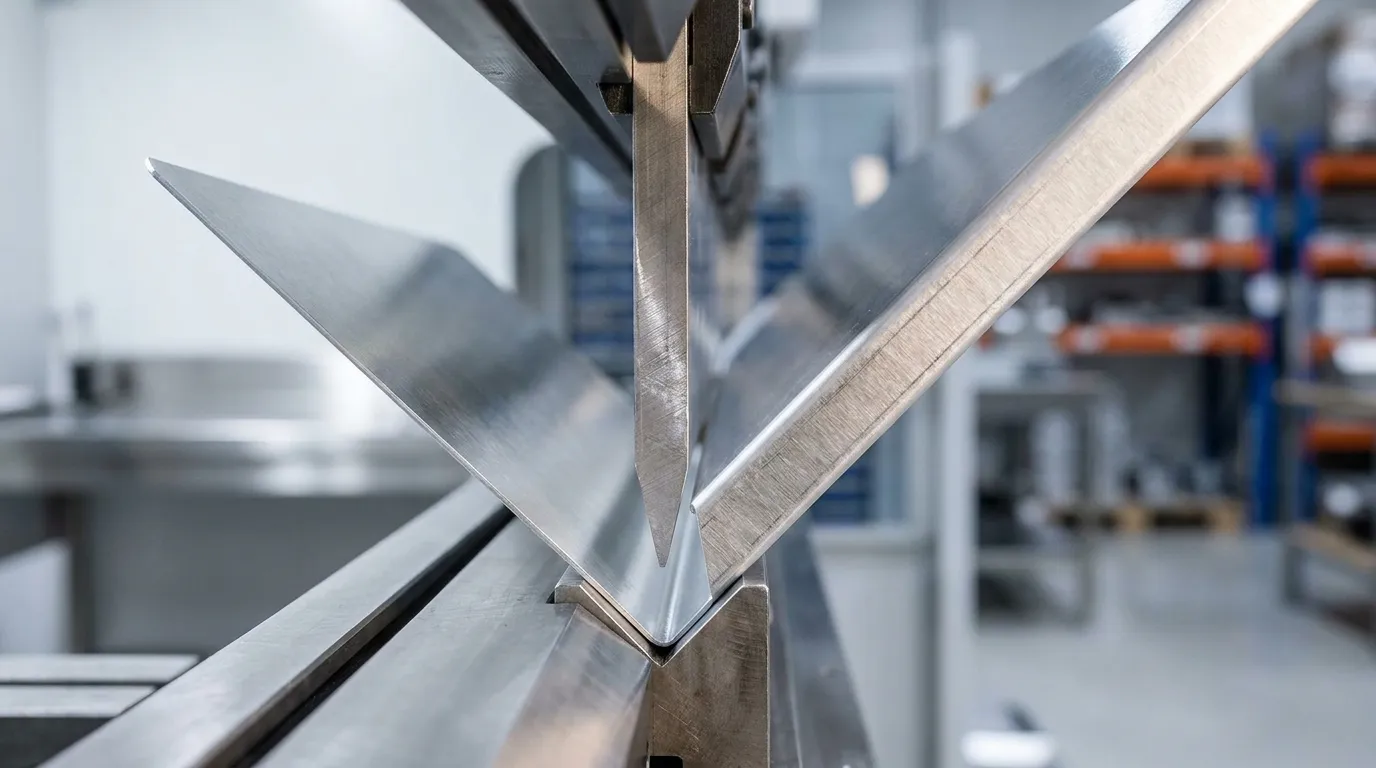
Minimum Bend Radius Guidelines for Sheet Metal Enclosures
Selecting the correct minimum inside bend radius is the first DFM checkpoint for any sheet metal enclosure. Radii that are too tight crack the outer fiber. Radii that are unnecessarily generous waste material and increase flange length. The following rules align bend radius with material behavior and shop tooling.
-
Apply material-specific multipliers rather than a single universal value. Minimum bend radius equals a material factor multiplied by material thickness, where the factor is 1 times for mild steel, 1.5 times for stainless steel, 0.8 times for aluminum 5052, 1.5 times for aluminum 6061 and 1 times for copper.
-
Orient bends perpendicular to the rolling grain. Bending parallel to the grain increases cracking risk on the outer surface and undermines the radius targets set in the first step.
-
Account for springback by material. Springback is highest in aluminum, medium in stainless steel and lowest in mild steel, so K-factor compensation in flat-pattern calculations keeps the final bend angle within tolerance.
-
Validate with test bends on production-representative samples before committing to full runs, particularly on tight-tolerance enclosures, because springback and grain effects vary by lot.
Fabcon engineering team reviews bend radius specifications against in-house tooling inventory during DFM collaboration, catching radius-tooling mismatches before they generate scrap or schedule delays. Submit drawings for a bend radius review.
Hole-to-Bend Distance Best Practices for Clean Formed Features
Correct hole placement relative to bend lines protects hole shape and position during forming. Holes placed too close to a bend line distort during press brake forming, shifting from round to oval and moving out of positional tolerance. Correcting distorted holes after forming requires secondary drilling or reaming, which adds cost and extends timelines.
-
Maintain a minimum hole-to-bend clearance of 2 times material thickness from the nearest bend line to prevent deformation and positional shift.
-
For tighter clearances, add relief cuts adjacent to the hole rather than moving the bend line. This approach preserves enclosure geometry while protecting hole integrity.
-
Apply a minimum of 3 times material thickness from hole edge to bend when hole positional accuracy is assembly-critical, such as for mating hardware or alignment pins.
-
Specify hole diameter tolerances consistent with process capability so punching, laser cutting and any post-processing can meet the print without unnecessary scrap.
Early DFM review by Fabcon engineering team flags hole-to-bend violations before tooling is programmed, which removes the rework loop that fragmented vendor chains often discover only after parts are formed.
Bend Relief and Flange Length Requirements for Reliable Forming
Correct bend relief and flange length prevent tearing and angle variation at corners. Bend relief cuts prevent material from tearing at the intersection of two adjacent bends. Flange length must be sufficient for the press brake tooling to grip and form the part accurately.
-
Add bend relief at every corner where two bends meet. Relief width should equal at least the material thickness, and relief depth should extend past the bend line by at least the material thickness.
-
Maintain a minimum flange length of 4 times material thickness to allow consistent press brake tooling contact and repeatable bend angle.
-
Avoid flanges shorter than the minimum, because they produce inconsistent bend angles and increase angular tolerance deviation beyond the typical range achievable in standard air bending.
-
Include flat-pattern information with every formed drawing. Omitting flat-pattern data increases dimensional deviation risk on multi-bend parts because each shop applies different default K-factor assumptions.
These rules stabilize corner geometry, reduce tearing risk and support predictable bend angles across production lots.
Tolerance Stack-Up and Hole Spacing Considerations in Enclosures
Tolerance stack-up is the accumulation of dimensional variation across multiple features. In sheet metal enclosures, stack-up across bends is the primary cause of assembly interference and rejected parts. A structured tolerance strategy controls this accumulation from general limits through coating.
-
Apply ISO 2768-m as the general tolerance standard for non-critical sheet metal features, reserving tighter grades for assembly-critical dimensions only.
-
Within that framework, separate critical fit dimensions from non-functional features. Tolerance stacking across bends and complex formed features is a core cause of part rejection even when individual features are within tolerance, so critical dimensions need focused control.
-
Use ANSI Y14.5 GD&T for geometric control on complex assemblies. GD&T better defines perpendicularity, flatness and true position than blanket tolerances and ties directly to the critical dimensions identified in the previous step.
-
When applying GD&T to formed parts, account for K-factor accuracy. A K-factor error of 0.05 produces approximately 0.3 to 0.5 mm error per 90 degree bend. On a part with six bends this can accumulate to 1.8 to 3 mm of total dimensional error, which can cause assembly failure.
-
Account for coating buildup on mating surfaces. Powder coating and paint add measurable thickness that affects hole sizes, mating surfaces and overall fit, so designs need tolerance adjustments even after dimensional limits are set.
Fabcon AS9100D quality system provides full dimensional traceability across fabrication, finishing and assembly, giving engineering and procurement teams the data needed to verify stack-up compliance at every stage of the build.
Self-Clinching Fasteners and Welding Reduction Strategies
Fastener strategy has direct impact on cost, distortion and scalability. Welding introduces heat distortion, post-weld grinding and secondary inspection steps that add cost and extend timelines. Designs that replace welds with formed features and pressed-in hardware are faster to produce and easier to scale.
-
Specify self-clinching PEM fasteners. Nuts, studs and standoffs pressed in during the punching stage provide fastening options that avoid welding and support design complexity without additional assembly steps.
-
Replace welded gussets with CNC-bent flanges and tabs wherever structural requirements permit. CNC bending reduces part count by combining multiple features into single formed components, which simplifies assembly and lowers total cost.
-
Reserve welding for seams and reinforcements where no formed alternative exists. Limiting welds reduces costs and lead time by removing secondary operations such as grinding and polishing.
-
Use interlocking tabs and slots to self-locate enclosure panels before any fastening operation. This approach reduces fixturing time and improves positional repeatability.
-
Confirm PEM hardware compatibility with the specified material thickness and coating process before releasing drawings to production so hardware performance matches field conditions.
Fabcon one-roof model covers fabrication, hardware insertion, finishing and light electromechanical assembly. This structure compresses the overall build cycle and reduces quality-control gaps that often appear when welding, grinding and coating move across multiple vendors. Discuss fastener strategy and welding avoidance for current enclosure programs.
Transitioning from Prototype to Production with One Fabricator
The prototype-to-production transition is where DFM decisions convert into program-level risk or stability. Designs validated at a quick-turn shop may not transfer cleanly to a production fabricator with different tooling, material stock and forming practices.
Prototyping at the intended production manufacturer preserves validated tooling and reduces supplier-switching risk because process capabilities, K-factor assumptions and material stocks remain consistent across both phases. This consistency makes prototype validation essential, because skipping it risks late design changes, tooling damage and production delays.
To control that risk, a formal first-article inspection of representative enclosures measured against every drawing dimension is required before committing to a production run after any drawing revision or manufacturer change. When this workflow is followed, DFM-driven redesigns often deliver meaningful cycle-time and piece-part cost reductions.
Fabcon supports programs from initial prototype through mid-volume production using flexible manufacturing cells that adapt to changing volumes, mixed SKUs and evolving bills of materials without high minimums or rigid onboarding. ISO 9001:2015 and AS9100D quality systems govern every stage of the build, providing the traceability and first-article documentation that aerospace, defense, medical and energy procurement teams require. Mid-volume, high-mix demand patterns are expanding across U.S. infrastructure, medical, energy, transportation, aerospace and defense sectors, and Fabcon agile production model is structured to meet that demand without the friction of supplier transitions.
Frequently Asked Questions
What value do ISO 9001:2015 and AS9100D certifications provide for sheet metal enclosure programs?
ISO 9001:2015 establishes a documented quality management system covering process control, corrective action and continuous improvement across fabrication, finishing and assembly. AS9100D adds aerospace-specific requirements including risk management, configuration control and full part traceability from raw material to shipped assembly. For procurement teams in aerospace, defense, medical and energy sectors, these certifications reduce audit burden, satisfy regulatory requirements and provide documented evidence that dimensional and cosmetic specifications were verified at every production stage. They also support first-article inspection documentation and provide the traceability records needed for failure analysis if field issues arise.
How does working with a single vertically integrated fabricator reduce supply chain risk compared to managing multiple vendors?
A fragmented vendor chain, with separate suppliers for sheet metal, coating, hardware insertion and assembly, introduces handoff delays, quality finger-pointing and coordination overhead at every interface. When a dimension is out of tolerance, each vendor can attribute the defect to the previous supplier, which extends resolution time. A single vertically integrated partner owns the entire build sequence under one quality system, so dimensional data from fabrication informs finishing tolerances, and assembly alignment issues are resolved internally rather than across purchase orders. This consolidation reduces the number of active supplier relationships, simplifies incoming inspection and provides a single point of accountability for program execution.
What is the difference between a job shop and a full-service sheet metal fabrication partner for enclosure programs?
A job shop typically operates as a build-to-print vendor, forming and cutting parts to a provided drawing without engineering input or downstream services. The customer remains responsible for DFM review, finishing, hardware insertion, assembly and logistics coordination across separate suppliers. A full-service fabrication partner provides DFM collaboration before drawings are released, performs in-house finishing such as powder coating and wet paint, inserts self-clinching hardware, completes light electromechanical assembly and manages fulfillment under one quality system. For mid-volume, high-mix programs where design iterations are frequent and time-to-market pressure is high, the full-service model reduces total program cost by eliminating rework from DFM gaps and compressing the build cycle by removing inter-vendor transit and inspection steps.
What tolerance expectations are realistic for production sheet metal enclosures?
General sheet metal fabrication produces linear dimensional tolerances in the range of ±0.1–±0.5 mm, hole position tolerances of ±0.1–±0.3 mm and bend angle tolerances of ±0.5°–±2° under standard air-bending conditions. Dimensions that span multiple bends accumulate variation and are held to looser tolerances than single-feature dimensions. Tolerances tighter than ±0.05 mm on sheet metal features typically require secondary CNC machining and can increase part cost significantly with no functional benefit when applied to non-critical features. The recommended approach is to apply ISO 2768-m as the general standard, use GD&T true position for assembly-critical holes and reserve tight tolerances for the specific dimensions that drive fit and function. Coating buildup on mating surfaces must also be factored into tolerance calculations before drawings are released.
How should material selection affect enclosure DFM decisions?
Material selection affects bend radius, hole-to-bend clearance, springback compensation, coating compatibility and structural wall thickness at the same time. Mild steel offers forgiving forming characteristics and low material cost, which makes it the default for general enclosures. Aluminum 5052 is the preferred aluminum alloy for enclosures requiring weight reduction and moderate corrosion resistance, with better formability than 6061. Stainless steel provides corrosion resistance and strength in harsh environments but work-hardens rapidly, which requires larger bend radii and more precise tooling setup. Thinner gauges suit non-structural covers and access panels, while thicker material is appropriate for structural frames and mounting surfaces. Material selection should be confirmed with the fabricator during DFM review because in-house material stock, tooling inventory and process capability vary by alloy and thickness.
Next Steps: Request a DFM Review
Applying enclosure design DFM sheet metal rules at the drawing stage reduces rework, compresses timelines and produces enclosures that meet functional, tolerance and finish requirements at production scale. Fabcon engineering and quoting teams review submitted drawings for bend radius compliance, hole-to-bend clearance, tolerance stack-up risk, fastener strategy and finishing compatibility, and provide actionable feedback before tooling is programmed or material is ordered. With ISO 9001:2015 and AS9100D quality systems, in-house finishing and light electromechanical assembly and flexible production cells that scale from prototype to mid-volume without high minimums, Fabcon supports program execution from first article through production release while minimizing supplier transitions. Submit drawings for a DFM review today.