
Key Takeaways
-
Select material thickness so the minimum hole diameter matches the thickness. This helps prevent distortion during laser cutting and punching.
-
Use minimum bend radii of 1T for mild steel and 3T to 5T for high-strength aluminum to reduce cracking and maintain strength.
-
Place holes at least 1.5T from edges and 2T plus bend radius from bends to limit deformation during forming.
-
Plan nesting, tab-and-slot features, and laser kerf allowances carefully to cut material waste and lower assembly costs.
-
Use Fabcon’s vertically integrated facilities for comprehensive DFM reviews. Request a design evaluation to identify improvements before production.
Essential Sheet Metal DFM Best Practices for Real-World Production
Effective sheet metal design for manufacturability focuses on material behavior, tooling limits, and process capabilities. These practices reduce failures and prepare parts for efficient production and assembly.
1. Material Selection and Thickness Guidelines
Choose materials and thicknesses that match your available manufacturing processes. For laser cutting and CNC punching, keep minimum hole diameters equal to material thickness to prevent distortion, which supports clean cuts without deformation. Thicker materials improve structural integrity, yet they also demand more forming force and larger bend radii, which affects tooling choices and design flexibility.
2. Minimum Bend Radius Requirements by Material
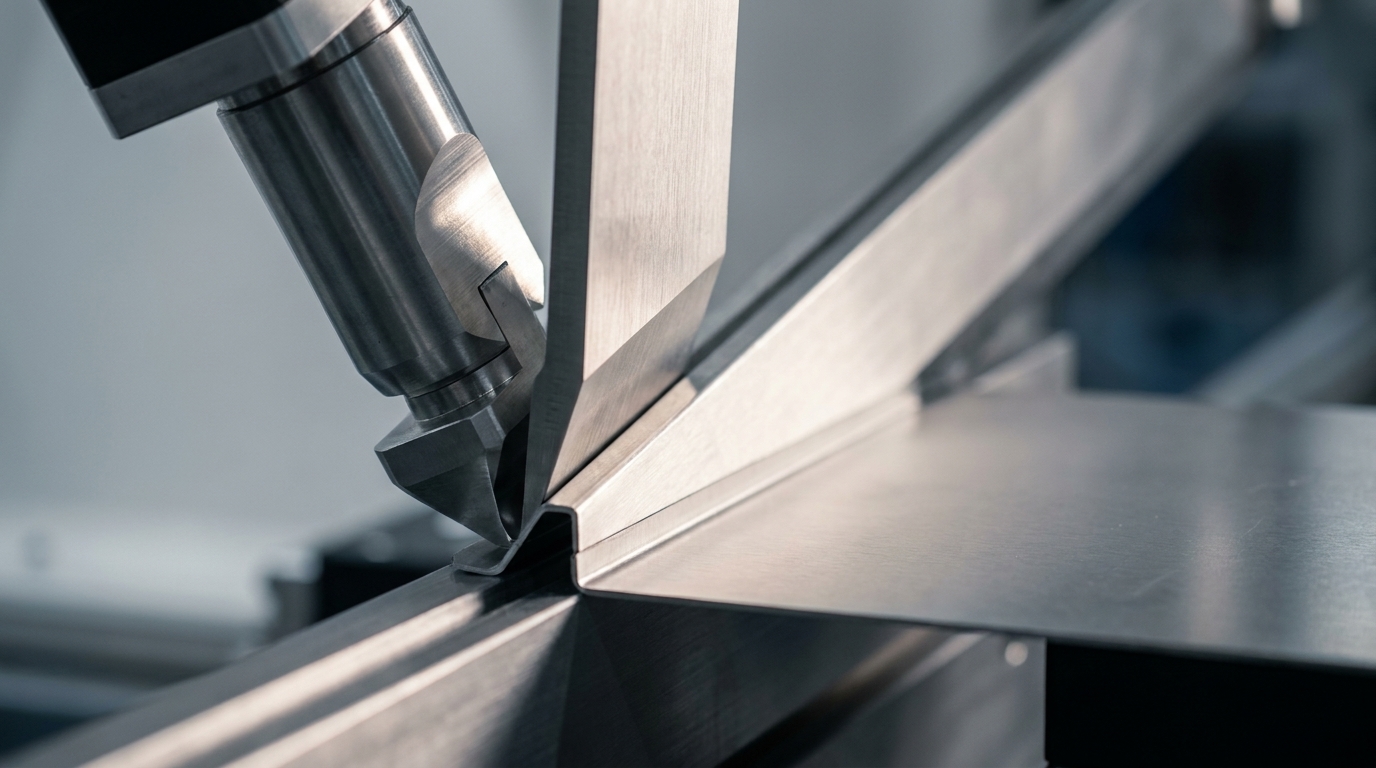
Bend radius strongly influences part strength and manufacturing feasibility. Many guidelines recommend a minimum bend radius of at least 1T for mild steel, where T equals material thickness. High-strength aluminum alloys behave differently under stress and crack more easily at tight bends. For 7075-T6 aluminum sheet, the recommended minimum bend radius is approximately 5T or greater depending on thickness to prevent microcracks that cause fatigue failure. Sharp bends below these thresholds increase the risk of structural weakness and dimensional inconsistency.
3. Hole and Slot Placement Rules That Prevent Distortion
Proper hole placement protects part integrity during forming. JLCCNC’s 2026 design guidelines recommend hole edge to sheet edge distance of at least 1.5T for standard applications. For holes near bends, RPProto specifies a minimum distance of 2T plus bend radius from the bend tangent line for holes under 1 inch diameter, and 2.5T plus bend radius for larger features. These spacing rules help prevent hole distortion and cracking during forming.
4. Nesting Strategies That Cut Material Costs
Smart part layout on sheet stock has a direct impact on material cost. High-efficiency nesting software keeps scrap rates low compared to manual layouts. Design parts with consistent orientations and avoid overly complex cutouts that leave unusable remnants. Look for ways to share common edges or interlock profiles so multiple parts fit together efficiently on each sheet.
5. Tab and Slot Design for Fast, Repeatable Assembly
Tabs and slots support efficient assembly and reduce hardware requirements. Design guidelines call for appropriate tab width and slot clearance that match standard fit conditions. To prevent edge tearing during assembly, maintain edge distance of at least 2T from slot boundaries to sheet edges. When you use multiple tabs, space them far enough apart to distribute loads evenly and avoid stress concentration at a single connection point.
6. Laser Cutting Details That Improve Fit and Finish
Laser cutting delivers high precision but needs specific design allowances. Account for kerf width, typically 0.1 to 0.3 mm, in critical dimensions, especially for tab-and-slot assemblies that must fit tightly. Using nitrogen for stainless steel cutting costs more than oxygen but eliminates secondary grinding by producing cleaner edges. Design parts to reduce piercing points and create efficient cutting paths that shorten cycle times.
7. Forming Allowances, K-Factors, and Flat Pattern Accuracy
Accurate flat patterns depend on correct bend allowance and K-factor values. ADHMT recommends an internal bend radius of about 1T for press brake bending to balance stress distribution and dimensional stability for many materials. Import empirical bending tables into your CAD system so critical dimensions stay within tolerance after forming. This approach reduces trial-and-error during first article builds.
8. Tolerance Management That Controls Cost
Set tolerances based on function instead of defaulting to tight values. Tighter bending and feature tolerances increase setup time, inspection effort, and scrap rates. Reserve strict tolerances for critical features such as mounting holes, mating surfaces, and sealing interfaces. Keep sheet thickness ranges within about ±0.05 mm for a given part family so bend angles remain consistent across production runs and fixtures stay valid longer.
9. Edge Finishing and Hemming Built into the Design
Plan edge treatments during the initial design stage, not as late add-ons. Simple edge breaks remove sharp edges for safer handling, while hems increase stiffness and improve perceived quality. Design hems with proper relief gaps at corners to prevent material buildup and wrinkling. Consider how these edge treatments change overall part dimensions and assembly clearances so mating components still align correctly.
10. Multi-Axis Bend Planning for Complex Parts
Beyond edge details, complex geometries introduce another layer of design work. Parts that require multiple bends need careful sequence planning to avoid collisions and rework. ADHMT recommends a V-die opening width of 8T for low-carbon steel, with 6T for soft aluminum and 10T to 12T for high-strength materials. Verify clearance between formed features and check that previously bent flanges do not interfere with tooling during later bends.
11. Designing for Finishing and Assembly Integration
Design parts so finishing and assembly steps fit smoothly into the workflow. Provide drainage holes for chemical processing, mask critical surfaces that must remain bare, and confirm that coating thickness will not conflict with assembly tolerances. A 40 μm powder coat costs less than an 80 μm coating while still protecting most applications effectively. These decisions keep both appearance and function consistent across builds.
12. Planning for Volume Changes and Process Shifts
Design flexibility into parts so they can scale with demand. Avoid features that require custom tooling when volumes are low, since those investments rarely pay off early. At the same time, do not oversimplify parts that will later move into high-volume production, where stamping or progressive dies may become practical. Plan how designs can transition from prototype laser cutting to production stamping as quantities grow.
Advanced DFM for Vertically Integrated Manufacturing
Advanced sheet metal DFM looks beyond single operations and considers the full manufacturing ecosystem. Vertically integrated facilities like Fabcon’s 220,000 square foot operation coordinate design optimization across fabrication, finishing, and assembly in one location.
Design for electromechanical assembly by including wire routing channels, component mounting features, and access panels in the first layout. These features reduce late-stage modifications during assembly integration. For EV infrastructure enclosures, treat cable entry points, grounding locations, and thermal management features as core design elements instead of add-ons.
Prototype-to-production handoffs work more smoothly when tooling and processes stay consistent. When fabrication, finishing, and assembly happen in the same facility, design changes can be tested quickly without managing multiple suppliers. This integration shortens feedback loops and reduces the tolerance stack-up issues that often appear in multi-vendor programs.
After you stabilize internal tolerances, focus on how parts interface with other components in the final assembly. Design mounting features, alignment aids, and service access points that simplify both initial assembly and field maintenance. Connect with our engineering team to discuss how integrated manufacturing can support your specific design requirements.
Common Design Pitfalls and How to Avoid Them
The most expensive mistakes often appear early in the design cycle. Poor DFM practices can drive a large share of engineering change orders during the first month of production. When suppliers handle fabrication, finishing, and assembly separately, engineers must coordinate multiple vendors, which slows decisions and increases quality disputes.
Keep design work connected to real manufacturing capabilities. Involve fabrication partners early to confirm assumptions and uncover simpler alternatives. Small adjustments such as shifting hole locations or reordering bend sequences can significantly reduce complexity, scrap, and cycle time.
Projects that include collaborative DFM reviews before design release tend to launch more smoothly. These sessions reveal potential issues while changes remain inexpensive and quick to implement.
Submit your designs for a comprehensive DFM evaluation that highlights cost-saving opportunities before you commit to tooling.
Frequently Asked Questions
What are the current sheet metal bending guidelines for different materials?
Modern bending guidelines vary by material type, strength, and grain direction. For mild steel, a minimum bend radius around 1T works for many applications when bending across the grain. High-strength aluminum alloys such as 7075-T6 often need 3T to 4T minimum radius to prevent surface cracking. Stainless steel typically requires 1.5T to 2T depending on grade and temper. Always review grain direction, since bending parallel to grain usually needs larger radii than bending across it.
What are the standard hole placement rules for sheet metal fabrication?
Hole placement rules depend on forming steps and part function. For general use, keep hole edges at least 1.5 times material thickness away from sheet edges. Near bends, position holes at least 2T plus bend radius from the bend tangent line for holes under 1 inch diameter, and 2.5T plus bend radius for larger openings. These distances help maintain structural strength and reduce distortion around holes during forming.
How do I optimize sheet metal designs for laser cutting efficiency?
Laser cutting efficiency depends on material utilization, cut quality, and cycle time. Use consistent material thickness across a part family to reduce setup changes. Limit very small holes and intricate details that slow cutting speeds or require micro-piercing. Account for kerf width, typically 0.1 to 0.3 mm, in tight-fit features. Group similar parts for efficient nesting and shared cut lines, and select cutting gases that match your material and edge quality needs.
How does vertical integration improve sheet metal DFM outcomes?
Vertical integration removes many coordination and quality issues that appear with multiple suppliers. When fabrication, finishing, and assembly stay under one roof, design changes move into production faster because teams do not wait on external approvals or shipping. Shared quality systems apply consistent standards across all processes. This structure reduces tolerance stack-up, shortens lead times, and provides single-point accountability for the full build.
Where can I find reliable bend radius charts for different materials?
Reliable bend radius data usually comes from material suppliers, fabrication equipment manufacturers, and industry standards organizations. The most useful charts include specific material grades, tempers, and grain orientations. Many CAD platforms contain material libraries with validated bend allowance data that reflect real shop conditions. For critical parts, run bend tests with your exact materials and tooling to create custom parameters that hold up across production runs.
Implementing DFM for Manufacturing Success
Effective sheet metal DFM depends on understanding how design choices interact with real production constraints. The 12 practices in this guide address common failure modes and prepare parts for efficient fabrication and assembly.
Strong outcomes rely on early collaboration between design and manufacturing teams. The most cost-effective improvements happen during initial design phases, before tooling and fixtures lock in. Treat fabrication, finishing, and assembly requirements as core design inputs instead of late-stage corrections.
Fabcon’s vertically integrated approach removes many coordination challenges that slow multi-vendor projects. Our 45-plus years of precision fabrication experience across data centers, EV infrastructure, and medical devices support both performance and manufacturability goals.
Partner with Fabcon for comprehensive DFM support and upload your design to receive expert feedback on manufacturability and cost optimization.