Key Takeaways for 2026 Sheet Metal DFM
- Follow material-specific bend radii to prevent cracking and keep parts formable in demanding 2026 applications.
- Maintain hole-to-bend distances ≥ 2.5×T + R and edge distances ≥ 4×T to avoid distortion and tearing during fabrication.
- Plan parts around standard sheet sizes and 0.125″ spacing to reach 85%+ material utilization and reduce scrap.
- Use standard tolerances (±0.005″), weld access rules, and common hardware to cut costs by 20–30% and improve yields.
- Partner with Fabcon for free DFM reviews, integrated production, and faster launches in EV, medical, and data center programs.
1. Material Selection for EV, Medical, and Data Center Enclosures
Material selection sets the limits for every downstream DFM decision. Development of high-strength steel grades and advanced alloys is driven by demanding applications requiring enhanced mechanical properties, especially in EV infrastructure and medical devices.
For 2026 projects, focus on core properties such as strength, corrosion resistance, and weight. Mild steel supports cost-effective structural parts. Aluminum 5052-H32 provides corrosion resistance for outdoor or clinical environments. Stainless 304 delivers durability and cleanability for medical and food-contact assemblies. High-strength steels support crash and impact requirements in EV and transportation systems.
These material-specific behaviors directly affect bend radii, forming limits, and weld performance. Fabcon engineers work with design teams early, aligning material choice with forming, finishing, and assembly requirements so you avoid late-stage redesigns.
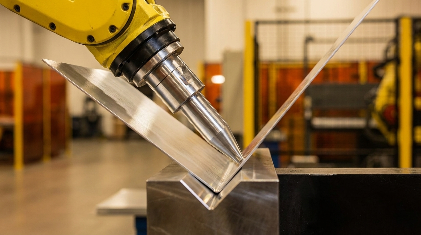
2. Bend Radii and Flange Length Rules After Material Choice
Once you lock in a material, bend radii and flange lengths define what you can form without cracking or distortion. Minimum bend radius requirements vary by material, and bending below those limits causes micro-cracks and part failure.
Minimum flange length for sheet metal bending is approximately 0.7 × V, where V is the lower die opening (typically 6T–8T, with T as sheet thickness). This guideline keeps parts from slipping into the V-opening during forming and maintains dimensional accuracy.
|
Material Type |
Min Bend Radius |
Min Flange Length |
Common Pitfall |
|
Mild Steel (A36) |
0.5× thickness |
4× thickness |
Over-bending creates springback and inconsistent angles |
|
Aluminum (5052) |
1× thickness |
4× thickness |
Sharp radii concentrate stress and crack during forming |
|
Stainless (304) |
1.5× thickness |
6× thickness |
Work hardening from tight bends makes rework difficult |
|
High-Strength Steel |
3–4× thickness |
8× thickness |
Micro-cracking from insufficient radius in structural parts |
Using these bend and flange rules early keeps flat patterns realistic and prevents last-minute changes when parts reach the press brake.
3. Hole and Cutout Spacing That Survives Bending
Correct hole and cutout spacing protects features from stretching, tearing, and distortion during bending. Minimum hole-to-bend distance follows Dmin ≥ 2.5 × T + R (T = sheet thickness; R = inner radius), which keeps tensile stress from elongating holes into oval shapes.
Keep bend-to-edge distance ≥ 4× material thickness to prevent deformation or tearing. For a 1.5 mm sheet, the nearest hole center should sit at least 6 mm from the inside of any bend.
Beyond hole-to-bend distances, maintain edge distances ≥ 2× material thickness and keep hole diameters ≥ material thickness for clean punching without deformation. Because these spacing rules interact, Fabcon’s engineering team reviews all clearances together during design review to catch conflicts that would cause cracking, distortion, or scrap.
4. Forming and Embossing Rules for Ribs, Text, and Louvers
Formed features such as ribs, embossed text, and louvers strengthen parts and add function, but they also introduce localized stress. Align tabs at least 45° to sheet grain to reduce fracture risk in cutouts and holes.
For embossed features, keep minimum wall angles around 1–2 degrees and avoid sharp internal corners that concentrate stress. Embossed text should be at least 0.020″ deep with 0.030″ minimum character width so it remains legible after powder coating or paint.
Louvers need consistent orientation relative to grain direction and enough clearance from bends and edges. These details matter on medical carts and data center enclosures, where airflow, labeling, and stiffness all depend on reliable forming.
5. Tolerances and Flat Pattern Development for Production
Standard tolerances and practices can reduce manufacturing costs by 20–30%. Recommended tolerances include ±0.13 mm (±0.005″) for sheared edge to hole and between two holes on one surface.
Flat pattern accuracy depends on bend allowance calculations that reflect material properties and tooling. These calculations use material-specific K-factors such as mild steel (0.33), aluminum (0.33), and stainless steel (0.38) to predict how much material the bend consumes. Accurate K-factors keep flat patterns aligned with real-world forming, which prevents scrap from blanks cut too large or too small and avoids fit issues during assembly.
Relax non-functional tolerances so production can run faster with less inspection. Apply tight tolerances only to dimensions that control assembly fit, sealing, alignment, or safety-critical performance.
Partner with Fabcon for assembly-integrated DFM that optimizes tolerances from day one—request your free design review.
6. Nesting Strategies That Cut Material Cost
Efficient nesting turns good part designs into cost-effective production by reducing scrap and sheet changeovers. Reduce material waste by maximizing standard sheet sizes and simplifying part design so layouts stay dense and repeatable.
Standard sheet sizes such as 4’×8′, 4’×10′, and 5’×10′ should guide overall part dimensions. Design parts to nest with at least 0.125″ spacing between profiles for laser cutting, and align parts with grain direction when strength or cosmetic appearance depends on it.
Fabcon plans nesting across entire production runs, not just single jobs, which improves material utilization on complex enclosure families and lowers per-part cost for EV infrastructure and medical device programs.
7. Welding and Joining Rules for Accessible, Repeatable Joints
Weld accessibility and joint design drive both weld quality and labor time. Optimize designs for laser cutting, punching, bending, and welding that match available equipment and tooling so joints can be produced consistently.
Design weld joints with at least 1″ clearance for standard electrode access and comfortable torch angles. Avoid backing welds in tight corners where grinding or inspection becomes difficult. Use a small set of joint types across the assembly to reduce setup changes and training requirements.
For structural or safety-critical parts, specify weld symbols and inspection levels that align with risk. Fabcon’s certified welders follow AWS D1.1 structural welding codes for critical infrastructure components.
8. Finishing and Surface Preparation for Coatings
Finish requirements influence edge treatments, hole design, and part geometry. Powder coating needs clean, deburred edges and holes for proper adhesion. Break sharp edges with 0.005–0.015″ chamfers or radii to improve coating coverage and handling safety.
Design parts to limit masking and rework during finishing. Avoid deep recesses and complex pockets that trap powder or create uneven film thickness. Consider finish access when placing holes, slots, and hardware so coaters can reach all critical surfaces.
Fabcon’s integrated finishing options, including powder coating, wet paint, and screen printing, keep finish quality consistent while removing delays from external vendors.
9. Assembly-Ready Design and Hardware Integration
Designs with error-proofing features such as asymmetrical positioning can cut manual assembly time by 30–50% and raise first-pass yield from 85% to over 98%.
Standardize on common hardware like #10-32 screws, 1/4-20 bolts, and widely available PEM fasteners. Size holes and edge distances to match hardware specifications and leave room for insertion tooling. Plan access for drivers, nutsetters, and future service so technicians can remove and replace components without disassembling entire systems.
Fabcon combines mechanical fabrication with electromechanical assembly, including wiring and component installation, so hardware choices and layouts support both build efficiency and long-term serviceability.
10. Prototype-to-Production Scaling for Growing Volumes
Prototype design choices either support or block smooth scaling to production. Integrating multiple sheet metal parts into one CNC-machined part can save 15–30% material cost and reduce processing time by over 20%, but that tradeoff must align with volume and lifecycle plans.
Confirm tooling needs early so production does not stall while you wait for dies or fixtures. Match processes to volume: laser cutting and forming for low to mid volumes, and progressive stamping or dedicated tooling for sustained high volumes. Keep critical features consistent between prototype and production so quality remains stable as volumes rise.
Fabcon’s agile production cells move from prototype to mid-volume production without the rigidity of large contract manufacturers, which supports evolving BOMs and changing demand in high-growth technology markets.
Sheet Metal Design Examples and Case Studies
Fabcon’s DFM collaboration delivers measurable gains across industries. For an EV power distribution enclosure, early optimization of bend sequences and material selection cut material waste by 25% and improved structural performance. The integrated approach removed three vendor handoffs and reduced lead time from 12 weeks to 6.
A medical cart assembly project showed the impact of assembly-integrated DFM. By refining hardware locations and wire routing during design, Fabcon reduced final assembly time by 30% and improved service access. Vertically integrated fabrication and assembly kept fabricated components aligned with electromechanical requirements.
For a data center infrastructure client, nesting optimization and standardized bend radii across multiple enclosure variants reduced tooling costs by 40% while holding the tight tolerances required for rack mounting.
DFM Guidelines PDF Checklist for 2026 Programs
Fabcon supports comprehensive 2026 DFM practices that cover material selection, bend calculations, hole spacing, and assembly integration. These practices include sheet metal design calculations, stamping formulas, and tolerance guidance tailored to medical devices, EV infrastructure, and data center hardware.
The checklist format enables quick design checks and helps engineering teams catch issues before release. Annual updates reflect new materials and manufacturing capabilities so your designs stay aligned with current shop-floor reality.
Sheet Metal DFM Frequently Asked Questions
What are the minimum bend radii for different sheet metal materials?
Minimum bend radii depend on material properties. Mild steel typically uses 0.5× thickness, aluminum 5052 uses 1× thickness, stainless steel 304 uses 1.5× thickness, and high-strength steels use 3–4× thickness. Staying at or above these values prevents cracking and protects part integrity.
How do I calculate proper hole-to-bend distances?
Use Dmin ≥ 2.5 × T + R, where T is sheet thickness and R is inner bend radius. This spacing keeps holes from distorting during bending. Also maintain edge distances ≥ 4× material thickness to reduce tearing at edges.
What tolerances should I specify for sheet metal parts?
Standard tolerances of ±0.005″ work for most features. Tighten tolerances only where function demands it, because overly tight specifications can erase the 20–30% cost savings that standard practices provide. Focus precision on dimensions that control assembly fit or function.
How can I improve material efficiency in my design?
Size parts to fit standard sheet formats such as 4’×8′, 4’×10′, and 5’×10′, and design for efficient nesting. Maintain 0.125″ minimum spacing between parts for laser cutting. Well-planned nesting can reach 85% or higher material utilization.
What lead times should I expect for DFM reviews?
Fabcon provides fast DFM feedback on design submissions. Early collaboration during design prevents costly changes later and shortens overall project timelines. The engineering team reviews manufacturability, suggests improvements, and supplies accurate cost estimates.
Conclusion: Move Faster with 2026-Ready Sheet Metal DFM
The three most critical 2026 DFM guidelines are smart material selection, accurate bend and flange rules, and assembly-focused design. These fundamentals prevent most redesign cycles that slow product launches.
Fabcon’s end-to-end DFM collaboration accelerates time-to-market by combining precision fabrication, finishing, and assembly in one operation. This integrated model removes vendor handoffs and keeps designs aligned from prototype through production.
Ready to improve your sheet metal development? Get Fabcon’s expert DFM collaboration with quotes delivered in 48 hours. Start your project review.